 A Think Robotics guide
Best Soldering Iron Temperature for ESP32 Camera Module Installation
A soldering iron kit set to 315-340°C (600-650°F) delivers the best results when installing ESP32 camera modules without damaging sensitive components.
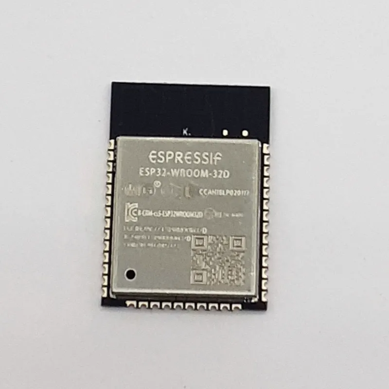
A soldering iron kit set between 315C and 340C (600 to 650F) is the commonly recommended range for soldering camera modules onto esp32-wroom-32 boards. This range melts lead-free solder reliably while keeping heat away from the sensitive CMOS sensor and surrounding circuitry that most ESP32 camera assemblies use.
Optimal temperature range for ESP32 camera modules
Most electronics work today uses lead-free solder, which needs a higher working temperature than older 60/40 tin-lead solder. ESP32 camera modules add an extra consideration because the image sensor sits close to your soldering point, and prolonged exposure well above this range risks damaging it. Staying near the low end of the range and limiting contact time gives you a margin of safety without starving the joint of heat.
Choosing a soldering iron kit for electronics
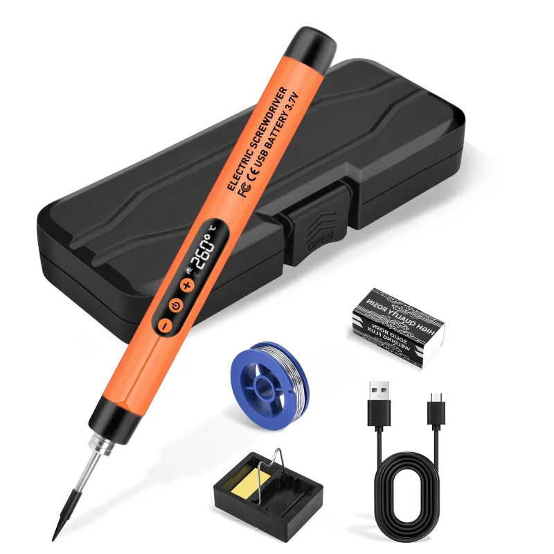
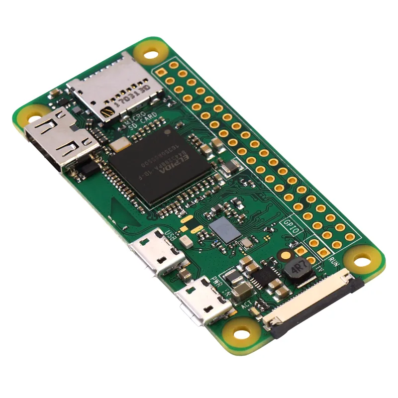
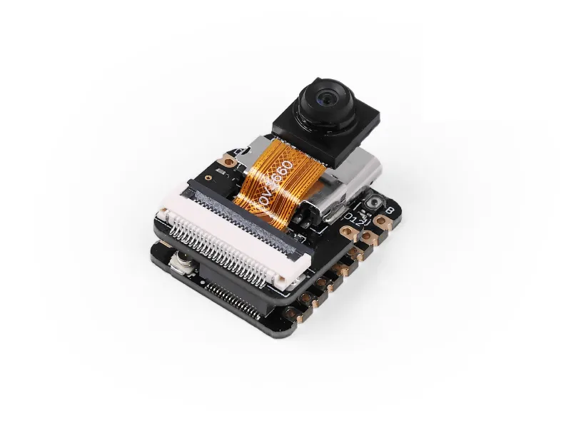
Not every soldering iron kit handles precision electronics equally well. Temperature control matters more than raw wattage when you are working with compact modules like an ESP32 camera board that might pair with a raspberry pi zero w or a seeed studio development board.
Features worth prioritizing:
- Digital temperature display and a stated accuracy tolerance
- An adjustable range that comfortably covers 200C to 450C
- Interchangeable chisel or conical tips between roughly 0.5mm and 1.5mm
- ESD-safe construction to protect sensitive ICs from static discharge
- A stable base that holds the iron securely between joints
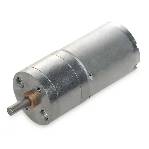
A temperature-controlled station is generally a better fit than a fixed-temperature pencil iron for this kind of work, since it lets you match the tip temperature to the job rather than guessing. If you also work with dc motor dc controllers or sensor arrays alongside a camera module, a kit with multiple tip sizes covers both fine-pitch pins and larger power pads without switching tools. For current pricing, check our discount code before you buy.
Step by step technique for camera modules
The right temperature only helps if your technique keeps stress off the module and its tiny pins.
Preparation:
- Secure the ESP32 board in a helping-hands fixture or on a silicone mat
- Pre-tin both the module pins and the PCB pads with a thin layer of solder
- Align the camera module using the mounting holes as a guide
- Check pin alignment under magnification before applying heat
Soldering:
- Let the iron stabilize at your chosen temperature before you start
- Touch the tip to the pad and pin together briefly, generally one to two seconds
- Feed a small amount of thin solder into the joint
- Remove the solder wire first, then the iron, in one smooth motion
- Let each joint cool undisturbed for a few seconds before moving the board
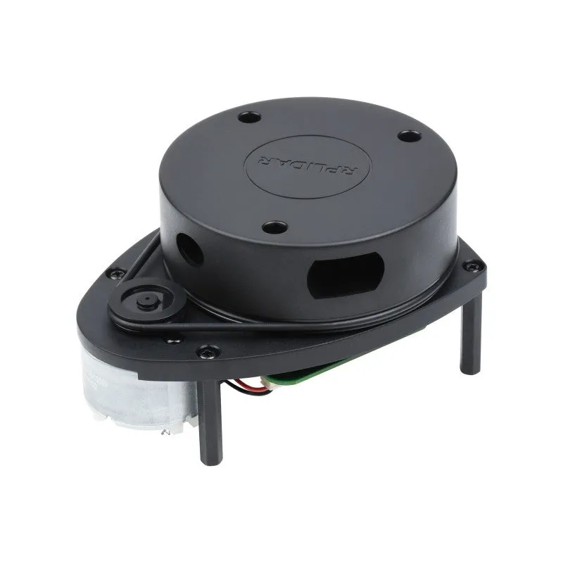
Work from the center pins outward to avoid stressing the module body, and if you are installing several components on one board, such as a camera alongside a lidar scanner, do the most heat-sensitive parts first while the board is still cool.
Common temperature mistakes and how to avoid them
Three temperature-related mistakes account for most ESP32 camera module damage during assembly.
Too hot. Running well above the recommended range makes solder flow faster, but it also risks delaminating the module’s circuit board layers or weakening internal connections you cannot see or repair. Symptoms can include image artifacts, color shifts or sensor failure that only shows up after the module is already installed.
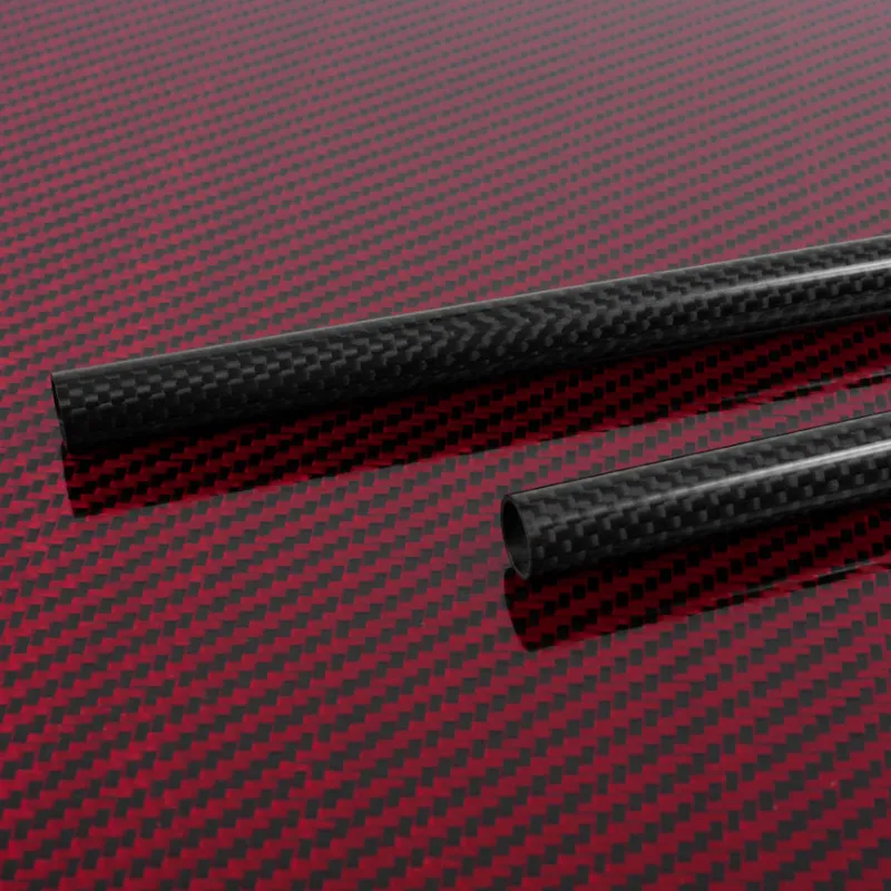
Too cold. Running below the recommended range produces dull, grainy joints that look solid but carry high resistance. A camera built this way may power on but fail under load, and cold joints are also more likely to crack from vibration if the board ends up in a moving robot chassis built with carbon fibre elements.
Inconsistent temperature. An iron without proper regulation can swing well off its set point as you work, so one joint flows cleanly while the next refuses to wet properly. Keeping the tip clean between joints, using brass wool or a damp sponge every few joints and re-tinning promptly, helps the iron hold a steady temperature.
Essential accessories for your soldering setup
A handful of supporting tools extend the life of your equipment and protect the work itself.
| Accessory | Purpose |
|---|---|
| Brass wool cleaner | Removes tip oxidation without thermal shock |
| No-clean flux pen | Improves solder flow on small pads |
| Tip tinner | Restores an oxidized tip and extends its life |
| Silicone work mat | Heat-resistant surface that protects components during assembly |
Keeping a couple of tip sizes on hand helps too: a fine conical tip suits the small pitch pins on a camera module, while a wider chisel tip speeds through the ESP32’s larger through-hole pins and power connections. If your build combines electronics with mechanical parts, such as mounting a camera in a polycarbonate pc enclosure or on 3d printing materials brackets, having tools organized in one kit keeps the iron from sitting idle at temperature between steps. Grab our code when you are ready to order.
Verifying your work after installation
Even careful soldering deserves a check before you close up an enclosure. Inspect each joint under magnification and look for a smooth, slightly concave fillet that flows from the pin onto the pad. Rework any joint that looks grainy, balled up or fails to wet the copper completely, rather than hoping an uncertain connection will hold.
Power up the board and run a basic camera initialization to confirm the sensor reports the correct resolution and captures frames consistently. If you are pairing the camera with other hardware, such as a pi zero w or a rasberry pi 5 for image processing, test the full data pipeline before you consider the hardware finished. Running the camera for a while and watching for noise or stuck pixels is a simple way to catch a marginal connection before it becomes a bigger problem later.
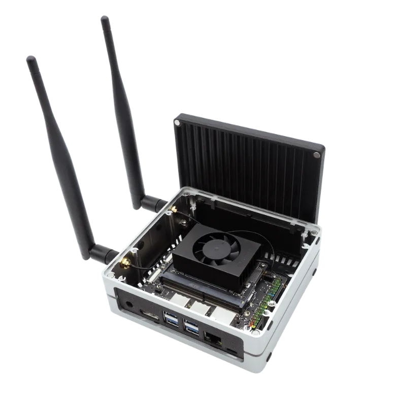
If your build is scaling up toward heavier compute, such as an nvidia jetson orin nano super developer kit carrier board, the same soldering discipline applies regardless of what is downstream from the camera module.
Questions
What temperature should I set my soldering iron for ESP32 camera modules?
A range of about 315C to 340C (600 to 650F) is a reasonable target. It melts lead-free solder efficiently while limiting heat exposure to the image sensor nearby.
Can I use a basic soldering iron without temperature control for this work?
A regulated, temperature-controlled iron is a better fit for ESP32 camera work than a fixed-temperature iron, since these modules need consistent, predictable heat and unregulated irons can run hot or fluctuate as you work.
How long should I hold the iron on each camera module pin?
Roughly one to two seconds is typical, enough for lead-free solder to flow and wet the joint without transferring excessive heat to the nearby sensor.
What is the difference between a soldering iron kit for electronics and a general-purpose kit?
Kits built for electronics tend to include finer tips, more precise temperature control and ESD-safe construction. General-purpose kits often have larger tips and looser temperature regulation, which suits heavier work better than delicate boards.
Why does my camera module fail after soldering looks successful?
A delayed failure usually points to a cold joint from too little heat, or heat damage from too much. Inspect joints under magnification and confirm your iron held a steady temperature in the recommended range during assembly.
Do other ESP32 components need a different temperature?
Most other ESP32 board components tolerate the same range comfortably. The camera module is generally the most heat-sensitive part in a typical build, so a setup that works safely for the camera will usually handle standard through-hole and surface-mount components too.
Products in this guide
 Shopping at Think Robotics? See the discount code
3% OFF All Orders
Shopping at Think Robotics? See the discount code
3% OFF All Orders
More in this series
Carbon Fibre vs Polycarbonate PC: Choosing Structural Materials for Robot Frames7 Aug 20265 minDo You Need a LiDAR Scanner for Your Robotics Project?7 Aug 20265 minESP32-WROOM-32 Not Connecting to WiFi: Troubleshooting Guide7 Aug 20264 minHow to Set Up the NVIDIA Jetson Orin Nano Super Developer Kit for AI Projects7 Aug 20266 minRaspberry Pi Zero W vs Pi Zero 2 W: Which Single-Board Computer Should You Choose?7 Aug 20265 min