 A MAXKGO guide
How to Wire a 4-in-1 ESC With a BMS for a Clean DIY Build
We walk through the complete wiring process for a 4 in 1 ESC with a BMS, covering schematics, power distribution, and the best components for a clean DIY build.
Wiring a 4 in 1 ESC with a BMS is the cleanest way to consolidate power distribution and motor control in a single DIY board or drone build. By combining four ESCs on one board and pairing it with a smart battery management system, you eliminate the rat’s nest of individual wires, reduce short risks, and gain centralized monitoring of your battery cells. We will walk through the exact wiring steps, component choices, and configuration tips so your build stays tidy and reliable from the first test ride.
Why Combine a 4-in-1 ESC With a BMS
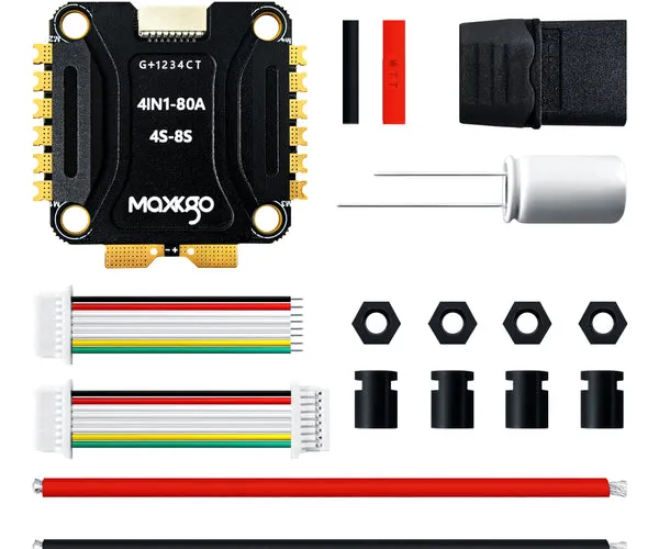
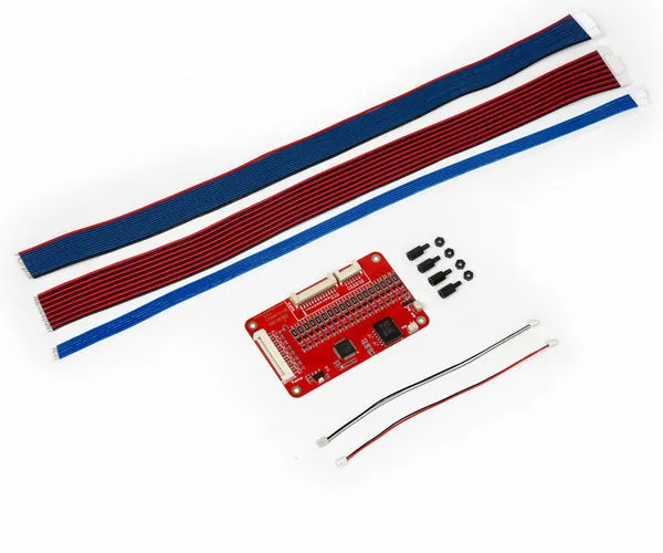
A 4 in 1 esc merges four individual motor controllers onto one PCB, which cuts solder points by more than half compared to separate ESCs. When you add a BMS like the 4 bms kart, you also get cell-level voltage monitoring and overcurrent protection for the whole pack. Together they give you:
- Fewer wires: One power input instead of four.
- Cleaner layout: The BMS connects directly to the main battery leads, and the 4-in-1 ESC sits on the same power rail.
- Better safety: The BMS handles low-voltage cutoff and balance charging while the ESC handles motor commutation.
- Easier troubleshooting: One board to check instead of four separate units.
This setup is especially popular in electric skateboards, longboards, and larger FPV drones where space is tight and reliability matters.
Wiring Diagram and Schematic Overview
Before you pick up a soldering iron, sketch out your power path. The general flow for a 4 in 1 esc schematic is:
- Battery pack → BMS (B+ and B- terminals)
- BMS output (P+ and P-) → 4-in-1 ESC main power pads
- 4-in-1 ESC motor outputs → individual motor phases (A, B, C per motor)
- Signal wires → flight controller or receiver (PWM or Dshot)
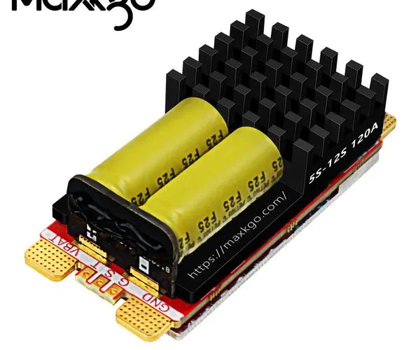
The BMS sits between the battery and the ESC so it can interrupt current if a cell drops too low or a short occurs. For a 12s esc system, the BMS must support 12 series cells (44.4 V nominal). The ltc6813 battery monitor IC is a common choice for high-cell-count BMS boards because it handles accurate voltage readings across all series groups.
Choosing the Right Components
Not every 4-in-1 ESC works well with every BMS. Here is what we look for when matching parts for a clean build.
| Component | What to Look For | Recommended Option |
|---|---|---|
| 4-in-1 ESC | 80 A continuous, 12S capable, solder pads for main power | 80a 4 in 1 esc |
| BMS | 12S, 60 A+ continuous, balance leads included | 4 bms kart |
| Battery | 12S LiPo or Li-ion pack with balance connector | onewheel pint battery module |
| Configurator | Open-source firmware with easy tuning | am32 configurator |
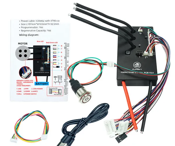
If you prefer a VESC-style controller, the flipsky 75100 and flipsky ft85bd are single-board options that pair well with a BMS, but you can also use the 4-in-1 ESC for a cleaner footprint.
Step-by-Step Wiring Process
Follow these steps for a 4 1 esc installation that stays organized and safe.
1. Prepare the Battery and BMS
Solder the main battery positive and negative wires to the BMS B+ and B- pads. Then solder the balance leads from each cell group to the corresponding BMS balance port. Double check the order: cell 1 goes to the first pin, cell 2 to the second, and so on. A reversed balance wire can damage the BMS immediately.
2. Connect BMS Output to the ESC
Run a thick silicone wire (10 AWG or thicker for high current) from the BMS P+ and P- pads to the main power input pads on the 4-in-1 ESC. Keep these wires as short as possible to reduce voltage drop and inductance. Add a pre-charge resistor or anti-spark connector if your BMS does not have a soft-start feature.
3. Wire the Motor Phases
Each motor gets three phase wires (A, B, C) soldered to the corresponding output pads on the 4-in-1 ESC. The order does not matter at this stage because you can swap any two wires in the configurator to reverse motor direction. Tin the pads and wires first, then use a temperature-controlled iron at 350°C for a solid joint.
4. Route Signal Wires
Connect the signal ground and PWM signal wires from the 4-in-1 ESC to your flight controller or receiver. For a 4 in 1 esc drone build, use a single ribbon cable that carries signals for all four motors. In a skateboard build, you can use a simple PWM adapter or a VESC-compatible UART connection.
5. Configure the ESC
Open the am32 configurator (or your ESC’s firmware tool) and set motor timing, PWM frequency, and current limits. For a 12S pack, make sure the low-voltage cutoff aligns with the BMS cutoff voltage (typically 3.0 V per cell). Calibrate throttle endpoints if your ESC requires it.
4-in-1 ESC vs Individual ESCs
Many builders ask us about 4 in 1 esc vs individual configurations. Here is a practical comparison.
| Factor | 4-in-1 ESC | Individual ESCs |
|---|---|---|
| Wiring complexity | Low, one power input | High, four separate power pairs |
| Board size | Compact, single mount | Spread out, more frame space |
| Heat dissipation | Shared PCB, runs hotter | Each ESC has its own heatsink |
| Repair cost | Replace whole board | Replace one ESC only |
| Best for | Tight builds, clean look | High-power or test setups |
For most DIY builds where space is a priority, the 4-in-1 wins. If you are pushing extreme current (over 80 A per motor) or want modular redundancy, individual ESCs make more sense.
Tuning With AM32 and VESC Tools
Once the wiring is done, tuning is the final step. The best 4-in-1 ESC options support open-source firmware like AM32 or BLHeli_32. With the am32 configurator you can:
- Adjust motor timing: Lower timing for efficiency, higher for torque.
- Set current limits: Match the BMS rating to avoid tripping protection.
- Enable bidirectional mode: Needed for sensorless FOC and reverse.
- Log data: Monitor RPM, current, and temperature during test rides.
If you are using a VESC-based ESC such as the flipsky 75100 or flipsky ft85bd, the VESC Tool gives similar tuning options with a different interface.
Common Mistakes and How to Avoid Them
We have seen a few wiring errors show up repeatedly in DIY builds. Watch for these.
- Skipping the pre-charge resistor: Without it, the BMS capacitor bank pulls a huge inrush current that can blow the BMS fuse. Add a 100 ohm resistor in series with a momentary switch across the main power connector.
- Reversing balance leads: Always verify the pinout with a multimeter before soldering. One wrong wire can short a cell group.
- Using thin power wire: A 4-in-1 ESC pulling 80 A needs at least 10 AWG. Thinner wire heats up fast and wastes voltage.
- Forgetting the ground bridge: The signal ground between the ESC and controller must be connected. Floating ground causes erratic motor behavior.
Need a current price or a discount code for your build? Grab the code before you order parts.
Who This Build Suits Best
This wiring approach works well if you are building an electric skateboard, a mountainboard, or a large FPV drone that needs reliable power distribution. It also suits anyone who wants a 4-in-1 esc and flight controller integrated stack for a drone. If you are building a small 3-inch or smaller drone, a 4-in-1 ESC may be overkill, and individual 20 A ESCs would be lighter and cheaper.
For high-power applications like a 12S electric longboard, the 80a 4 in 1 esc paired with a matching BMS gives you the cleanest layout and the fewest failure points. We recommend checking the latest store pricing to see what fits your budget.
Final Checks Before Powering On
After everything is soldered and configured, run these checks.
- Measure resistance across the main power input with a multimeter. It should be above 1 k ohm before the capacitors charge.
- Verify each motor spins freely by hand with no binding.
- Power on the BMS first, then the ESC. Listen for the startup tone sequence.
- Test each motor at low throttle (10%) before going full speed.
If any motor stutters or fails to start, swap two phase wires and re-test in the configurator.
A clean 4-in-1 ESC with BMS wiring job is one of the most satisfying milestones in a DIY build. Take your time with the soldering, double check every connection, and you will end up with a board that runs reliably for hundreds of miles.
Questions
Can I use a 4-in-1 ESC with any BMS?
Not all BMS boards are compatible. You need a BMS that matches your battery voltage (6S, 10S, 12S) and can handle the peak current your 4-in-1 ESC draws. Check the current rating on both before wiring them together.
Do I need a flight controller with a 4-in-1 ESC?
It depends on your build. In an FPV drone, a flight controller handles signal routing. In a skateboard build, you can wire the 4-in-1 ESC directly to a receiver or PWM adapter without a separate flight controller.
What gauge wire should I use for a 4-in-1 ESC and BMS setup?
For the main power wires between the BMS and the 4-in-1 ESC, use 10 AWG or thicker silicone wire. Signal wires can be 22 AWG or smaller. Thinner power wire creates voltage drop and heat under load.
How do I configure the ESC after wiring it to the BMS?
Use the AM32 configurator or VESC Tool depending on your ESC firmware. Set the low-voltage cutoff to match the BMS cutoff (usually 3.0 V per cell), calibrate the throttle, and adjust motor timing as needed.
Is a 4-in-1 ESC better than separate ESCs for a DIY board?
A 4-in-1 ESC is better for clean, compact builds that do not exceed 80 A per motor. Separate ESCs are better for high-power builds where heat dissipation and modular repair are more important.
What happens if I wire the balance leads backwards to the BMS?
Wiring balance leads backwards can short a cell group and permanently damage the BMS or the battery. Always verify the pinout with a multimeter before soldering the balance connector.
Products in this guide
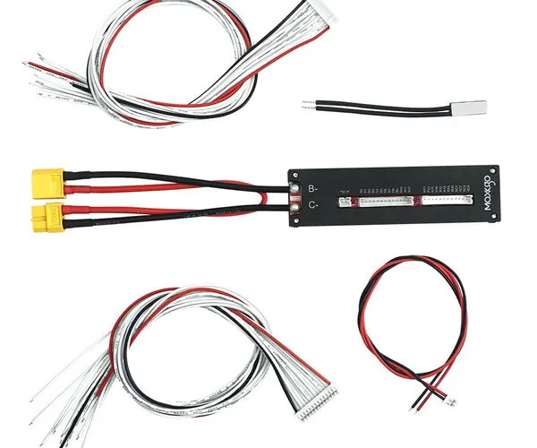
 Shopping at MAXKGO? See the discount code
2% OFF Sitewide
Shopping at MAXKGO? See the discount code
2% OFF Sitewide
More in this series
Can You Use a Onewheel Pint Battery Module With a Flipsky ESC?5 Sep 20265 minWhat to Look for in a 12S ESC for Your Electric Skateboard or E-Bike5 Sep 20264 minFlipsky FT85BD VESC ESC Not Working? Common Issues and Fixes5 Sep 20264 min4-in-1 ESC vs Individual ESCs: Which Is Right for Your Build?5 Sep 20266 minHow to Configure Your Flipsky 75100 ESC With the Am32 Configurator5 Sep 20264 min